I2C Displays on the CodeBot


The CodeBot has thirteen visible LEDs you can turn on and off with your Python code. You already know that – you’ve been through the awesome Python with Robots lessons to blink each of those. But if you are like me, you are thinking, “I need more LEDs!” Thirteen isn’t nearly enough. It’s not even close.
In this blog post I’ll show you how to connect a whopping 128 LEDs to the CodeBot with just four wires! And with a few lines of Python code, we’ll bring those LEDs to life.
Along the way, you’ll learn about I2C (pronounced “eye-squared-see”) and about talking to real life hardware devices. You’ll also learn some valuable experimenting techniques – how to tinker to answer the big questions like “how does this thing work?” You are the detective, and this little 8x8 LED matrix is your mystery device. Let’s snoop around under the covers and see what it can do!
Adafruit Displays
I used the 8x8 bi-color display matrix from Adafruit. Each of the 64 display elements is made from two LEDs – a red and a green. You can turn each on individually or turn them both on to make yellow (actually, it looks more like orange to me!)
Let’s do some math. That’s 8 * 8 elements * 2 LEDs each = 64 * 2 = 128 LEDs total.
I must warn you. Rather, I must excite you: if you buy one of these displays, some assembly is required. You have to … I mean you get to have the fun of … soldering the display to the circuit board. It’s super easy to do, and it is the perfect first soldering project if you’ve never soldered. You can buy a simple soldering kit with everything you need for less money than the display itself. For instance: https://www.amazon.com/Soldering-Iron-Kit-Temperature-Rarlight/dp/B07PDK3MX1.
Adafruit has a great “how to” page on this display showing you how to put it together, check it out here.
If you are a beginner, you can watch YouTube tutorials to get started with soldering. Or you can seek out a local “makerspace” in your hometown. The folks there will be eager to assist. Or heck, swing by our office here at Firia Labs and we’ll help you put your display together.
I2C Bus
The I2C bus is a simple way for a microprocessor to talk to low speed hardware devices. Data is sent back and forth on the bus serially (one bit at a time) with just two wires: a data line and a clock line.
Multiple devices can be attached to the same two-wire bus. Each device must have its own unique seven-bit address (0 - 127). The microprocessor talks to a device by first sending the address on the bus followed by one or more bytes of data. All the devices on the bus see the communication, but only the device with the target address reacts.
With so many chip makers and so many types of I2C devices, there are bound to be address conflicts. How do you connect two devices that have the same address? How do you connect three of these 8x8 displays at the same time if they all have the same address?
Most I2C devices allow you to select a different address by connecting one of the chip’s pins to high or low voltage. The Adafruit 8x8 display has three such pins, and you can change the address with three solder pads on the back of the display board. The Adafruit learning guide referenced above goes into great detail. Basically, you drop a blob of solder across the square pads to configure the desired address.

You see that chip with all the legs on the back of the board? That the HT16K33 chip. It is a generic I2C-LED driver chip made by Holtek that can be used in a variety of applications. Adafruit makes several display boards that use this same driver chip. We’ll explore more of them in a future blog post.

Connecting the Display
Place your handy Firia CodeBot Expansion Module onto your CodeBot. Place the four pins of the display somewhere on the top half of the board like you see in the image below. Leave a row or two at the top of the display to plug in the wires.
You’ll need four wires to connect the display board to your CodeBot. The four pins of the display are labeled at the top of the board. Connect “+” on the display board to the expansion connector’s “3.3V” plug. Notice there are TWO plugs labeled “3.3V”. Actually, there are two of everything – one on each side of the board. Both sides are wired together, and you can use either side for any signal.
Connect the “-” on the board to the expansion’s “GND” plug. The “C” on the display board is the “clock”. Connect it to “SCL” on the expansion. Finally, connect the “D” on the display board (“data”) to the “SDA” plug on the expansion. And that’s it!

Riding the Bus
You can jump right onto the CodeBot’s I2C bus using the Python REPL. You can send bytes on the I2C bus right there from the command line and experiment with the display live and in person.
Connect your CodeBot and open CodeSpace in your browser. Select “Show Debug Panel” from the “View” menu. Then select “Show Advanced Debug Panel” from the “View” menu. You’ll see the REPL window in the lower left hand corner of the CodeSpace page.
Enter some commands to get the Python juices flowing:

The CodeBot uses its I2C bus to talk to its accelerometer. You remember working with “botcore.accel” in the CodeBot lessons. Remember, you checked the accelerometer for movement and made an alarm. The “botcore.accel” has an I2C object it uses to talk to the bus. You can borrow that module’s object for your own use (it won’t mind).
Here is how to do it:
>>> from botcore import *
>>> i2c = accel.i2c
>>>
>>> i2c.scan()
[30, 112]
>>>
The I2C object has a “scan” method that returns a list of all devices on the I2C bus. The CodeBot only has one I2C device: the accelerometer at address 30. The second device, 112, is the display we just added to the bus! See? We are already talking to it.
If you run this same scan on the Firia CodeX, you’ll see four native devices. Your external display is the fifth.
>> i2c.scan()
[24, 25, 36, 41, 112]
Talking to the Display
When the display board powers up, the display is not turned on. You have to write three configuration values to the chip to get it going. For now, just paste in the four lines below. You can experiment with them later once you have the display running. And, if you have a free Saturday night, you can curl up on the couch with a laptop and some tea and read about all the chip’s features from the datasheet: https://cdn-shop.adafruit.com/datasheets/ht16K33v110.pdf.
ADDR = 0x70 # 112
i2c.writeto(ADDR, bytes([0x21]) ) # 0010_xxx1 Turn the oscillator on
i2c.writeto(ADDR, bytes([239]) ) # 1110_1111 Full brightness
i2c.writeto(ADDR, bytes([0b10000001]) ) # 1000_x001 Blinking off, display on
And then a line to turn on some LEDs:
|
 |
||
The writeto method writes a list of bytes to a device at the given I2C address. You specify “address” first followed by the list of bytes, and the code clocks the bits out onto the I2C bus. In the example above, I’ve shown numbers written in hex “0x21” and in decimal “239” and in binary “0b10000001”. You can use whatever number base feels most natural to you, but expect to see a lot of hex and binary when you look through the datasheet.
What’s up with all that “bytes” stuff? The writeto method expects a list of values to write to the bus, but it wants a list of bytes and not a list of integers. On the last line of code above, you see a familiar list of integers “[0,1,0,0,2,4,4]”. That’s just a regular old list – nothing special about that.
Python has a “bytes” type that is very efficient at holding a list of small unsigned integer values that are less than 256 (in other words, bytes). The memory footprint of the “bytes” list is as small as possible, and the code can walk through these lists much more quickly than it can a regular list. Small and fast: that’s why hardware functions like writeto require a “bytes” list.
The bytes(…) function takes a list of integers and returns a “bytes” list. It does the conversion from a regular list to the small/fast data structure wanted by the hardware methods. I could write a whole blog post on Python “bytes”. But for now, just build up your list of values in a regular list of integers and use the bytes(...) function to convert.
Back to the display. That last line of code in the example above is the key to lighting up the LEDs. Try tinkering with it on your own. Change the bytes and add more bytes. Here’s a hint: always make the first byte a 0 followed by exactly 16 other bytes.
The HT16K33 chip has 16 bytes of internal memory used to hold the state of the LEDs on the display. Each bit in that memory is one LED (0=off, 1=on). 16 bytes * 8 bits each = 128 LEDs.
The first byte you send, the “0”, is the starting address within the 16 bytes of LED memory. The 2nd byte you send goes to that address followed by the third and so on for all the bytes you send. If the internal address gets to 16, it wraps back around to 0. The easiest thing to do is to start at address 0 and write all 16 bytes in one command.
Let’s turn on all the LEDs. At this point you should switch to writing code in the code window and running it. I called my new file “LEDMatrix”.
from botcore import *
i2c = accel.i2c

ADDR = 0x70 # 112
i2c.writeto(ADDR, bytes([0x21]) ) # 0010_xxx1 Turn the oscillator on
i2c.writeto(ADDR, bytes([0xEF]) ) # 1110_1111 Full brightness
i2c.writeto(ADDR, bytes([0x81]) ) # 1000_x001 Blinking off, display on

data = [
    0, # The starting LED memory address
    0xFF, 0xFF, 0xFF, 0xFF,
    0xFF, 0xFF, 0xFF, 0xFF,
    0xFF, 0xFF, 0xFF, 0xFF,
    0xFF, 0xFF, 0xFF, 0xFF
]

i2c.writeto(ADDR,bytes(data))
Or how about we write 16 random values to the display twice a second? That’s a cool effect:
import random
import time
from botcore import *

i2c = accel.i2c

ADDR = 0x70 # 112
i2c.writeto(ADDR, bytes([0x21]) ) # 0010_xxx1 Turn the oscillator on
i2c.writeto(ADDR, bytes([0xEF]) ) # 1110_1111 Full brightness
i2c.writeto(ADDR, bytes([0x81]) ) # 1000_x001 Blinking off, display on

while True:
    data = [0] # Rember to start with the leading "0"
    for i in range(16):
        data.append(random.randint(0,255))

    i2c.writeto(ADDR,bytes(data))
    time.sleep(0.5)
Decoding the Matrix
Ultimately, you want to make a library for other programmers to use with their own displays. Take a minute to think about the design. What kinds of functions will people want from your library? What do YOU want from your library right now?
I’d like to have the ability to control individual pixels. I’d like to refer to them by their X,Y coordinate. Typically, computer displays have (X=0, Y=0) in the upper left. The lower right of the display is (7, 7). What about colors? Maybe something like 0=off, 1=green, 2=red, and 3=yellow. Now we can define the “set pixel” function’s signature. I’m thinking an API something like this:
def set_pixel(data, x, y, color):
    # Insert code here
The variable “data” is the 16-byte integer array ultimately going to the display. We could have our function write directly to the display, but this way we get to build up a display buffer pixel by pixel with multiple calls to “set_pixel”. Then we write all the pixels out at once with a single writeto command.
All 128 LEDs on the display map to bits in the 16 byte data buffer. Let’s see if we can figure out how they map without consulting the data sheets and schematics! First, let’s light up one LED by setting just one bit – the lower bit of the very first data byte:
|
 |
||
Ah! That’s a green LED on the far right column. How about the second bit in the first byte?
|
 |
||
That’s the next green LED down. How about the upper most bit in that first byte?
|
 |
||
That’s the bottom right of the first column. Looks like the first byte in the buffer is the green LEDs in that far right column– from least significant bit at the top to most significant at the bottom. What about the second byte? Any guesses? Let’s light up the first bit in the second byte.
|
 |
||
There are the red LEDs! Give them a try all the way down that second byte. Looks like the second byte in the buffer is the red LEDs in the far right column – from least significant bit at the top to most significant at the bottom.
Now the first bit in the third byte:
|
 |
||
There is the next column of green LEDs. At this point, I have a theory.
It looks like each column is defined by 2 bytes, the first byte of the pair is for the green LEDs and the second byte is for the red LEDs. Bit 0 of each is the upper LED. Bit 7 is the lower LED. The columns go from right to left.
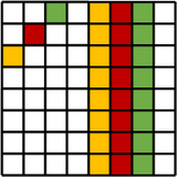
Let’s test the theory. Grab a piece of paper and graph out what you think the following code will produce on the display:
data = [0,     0,0, 255,0, 0,255, 255,255, 0,0, 1,0, 0,2, 4,4]
i2c.writeto(ADDR,bytes(data))
When you run the code, does the display match your paper?
Set Pixel Function
Now we can start coding up the “set_pixel” function. We’ll build the function up in small steps and test each step along the way.
Each column on the display is a pair of bytes in the 16-byte data buffer. The X coordinate identifies the pair of bytes, but we need to subtract the X coordinate from 7 to reverse the direction to left-to-right.
Once we find the pair of bytes, we set all the bits in both bytes. This is just a test of the first step:
|
 |
||
Try a few X coordinates to make sure the code identifies the correct column.
Next we deal with the Y coordinate, which identifies the bit number within the pair of bytes. We’ll use the shift-left operator "<<" to move a 1 bit into the desired position. Let’s test that by setting the bit in both target data bytes.
|
 |
||
Try out several X,Y combinations. Do you get the expected display? Can you code up a loop to draw a line from the upper left corner to the lower right corner?
Now we can deal with the color value. Right now we are setting the bits in both bytes. But we want to use the color value to decide which bits (if any) to turn on. We can say the color value passed into the function is a two-bit value. The lower bit is green – the other is red.
|
 |
||
Notice that our code can’t set a bit to 0. That means we can overwrite an existing pixel with a new color value. Give it a try. Set the pixel (4,7) to color 3 with one call to “set_pixel”, and then set it to to color 0 with another.
We need to modify our code to mask off a bit if it is zero. Instead of a bitwise OR to set the bit, we’ll use a bitwise AND to clear it:
def set_pixel(data, x, y, color):
    """
        color is 0=black, 1=green, 2=red, 3=yellow
        binary: 00=black, 01=green, 10=red, and 11=yellow
    """
    pos = 7-x
    pos = pos * 2

    bit = 1<<y # All 0s with a single 1
    mask = ~bit # All 1s with a single 0

    # Decode the color value into separate bits
    color_g = color & 1
    color_r = (color & 2) >> 1

    if color_g:
        data[pos] = data[pos] | bit
    else:
        data[pos] = data[pos] & mask

    if color_r:
        data[pos+1] = data[pos+1] | bit
    else:
        data[pos+1] = data[pos+1] & mask

data = [0,0,0,0,0,0,0,0,0,0,0,0,0,0,0,0]

set_pixel(data,2,5,1)
set_pixel(data,3,6,2)
set_pixel(data,4,7,3)
set_pixel(data,4,7,0)

i2c.writeto(ADDR,bytes([0]+data))
I like it! Now we can quickly identify any pixel by coordinate and color it by number. We don’t have to worry about the mapping details of bits to LEDs. Those details are hidden in our function.
The code still needs some error checking inside to handle bad values like X=-20, and it needs some documentation comments at the beginning to help the developers that use it.
Give our new function a spin. Plot some pixels on the display. Draw some pictures with pixels!
Here is a simple program to change random pixels on the display over time:
data = [0,0,0,0,0,0,0,0,0,0,0,0,0,0,0,0]
while True:
    x = random.randint(0,7)
    y = random.randint(0,7)
    c = random.randint(0,3)
    set_pixel(data,x,y,c)
    i2c.writeto(ADDR,bytes([0]+data))
    time.sleep(0.1)
Just the Beginning
This “set_pixel” function is just the beginning of your library. You can use it inside new library functions that draw horizontal and vertical lines.
Then you can build on the line-drawing functions to draw boxes. What would the signature of those functions be? Maybe this (maybe something better)?
def draw_line_horizontal(data, y, color):

def draw_line_vertical(data, x, color):

def draw_box(data, x, y, width, height, color):
I’ll leave these for you to code up.
How about a function to draw images on the display? Let’s do that next.
Images
You can use ASCII art to define an image within the code. That makes it easy for the developer to visualize what is going to the display. It makes it easy for you to create graphics – you don’t need a fancy bitmap editor!
For instance, here is the image of an alien from the old arcade Space Invaders. I’m using a list of strings to visualize it (the original image is black and white but I have added some colors):
invader_1 = [
    "...##...",
    "..####..",
    ".######.",
    "##*##*##",
    "########",
    ".$.##.$.",
    "$......$",
    ".$....$."
]
Each row in the list is a row on the display, and the characters in the strings will become colors on the display. Now we need to write our “draw_image” function to parse the image structure and translate ”.” to 0, “#” to red, “*” to green, and “$” to yellow. Python makes it easy:
def draw_image(data,img):
    for y in range(8):
        for x in range(8):
            c = img[y][x]
            # color = '.*#$'.index(c)
            if c=='#':
                color = 2
            elif c=='*':
                color = 1
            elif c=='$':
                color = 3
            else:
                color = 0
            set_pixel(data,x,y,color)

invader_1 = [
    "...##...",
    "..####..",
    ".######.",
    "##*##*##",
    "########",
    ".$.##.$.",
    "$......$",
    ".$....$."
]

data = [0,0,0,0,0,0,0,0,0,0,0,0,0,0,0,0]

draw_image(data,invader_1)

i2c.writeto(ADDR,bytes(data))
The outer loop steps over the rows of the list (the Y coordinate). The inner loop steps over the characters of the strings (the X coordinate). Each character in the string maps to a color value. Notice the commented code on line 5. That’s a quick way to map the characters to numbers. With that one line you could replace the entire if/else lines from 6 to 13.
How about some animation? The Space Invaders game has two images for this type of alien, and the game switches between the two images to make the creature walk. In this video you can clearly see the top row of aliens switching images: Space Invaders 1978 - Arcade Gameplay
We can do the exact same animation. First we’ll draw the two images into two data buffers. Then we’ll alternate drawing the finished buffers:
invader_1 = [
    "...##...",
    "..####..",
    ".######.",
    "##*##*##",
    "########",
    ".$.$$.$.",
    "$......$",
    ".$....$."
]

invader_2 = [
    "...##...",
    "..####..",
    ".######.",
    "##.##.##",
    "########",
    "..$..$..",
    ".$.$$.$.",
    "$.$..$.$"
]

data1 = [0,0,0,0,0,0,0,0,0,0,0,0,0,0,0,0]
data2 = [0,0,0,0,0,0,0,0,0,0,0,0,0,0,0,0]

draw_image(data1,invader_1)
draw_image(data2,invader_2)

while True:
    i2c.writeto(ADDR,bytes(data1))
    time.sleep(0.25)
    i2c.writeto(ADDR,bytes(data2))
    time.sleep(0.25)

More to Come
I’m super interested in your own projects and what you come up with! Drop me an email and show me what magic you’ve worked with the display.
In an upcoming blog, I’ll look at three more display boards made with the same HT16K33. You already know how to to talk to the chip – it’ll be a snap to figure out the LED mappings on the other boards. Until then, I wish you happy pixels!